Home Distillation of Alcohol (Homemade Alcohol to Drink)
Control Systems
Peter summarised the two alternative methods of control required..
When you have a reflux cooler on top of a packed column inside, you have
to regulate the small flowrate of the reflux cooling water system, to get
constantly 94 % alcohol during the whole proces.
The flowrate is regulated by the column top temperature.
When you have a reflux cooler on top of a packed column outside, you
have to regulate the flowrate of the reflux-distillate back into the
packed colunm, to get constantly 94 % alcohol during the whole proces.
The flowrate is regulated by the column top temperature.
I haven't yet found the need for elaborate control systems to regulate the
heat input or flow of cooling water etc. I believe that you first ensure
that the fundamental design is correct, matching the rate of cooling (and reflux
produced) to the heat input; once this is in balance the still should really
look after itself. Just set the cooling water flowrate, and check it every
half hour or so (remember the cardinal rule of never running a still
unattended !!)
I think the best solution is that suggested by Robert ...
.. What I have found works for me, is a temperature gauge in the
boiler; this allows me to see how much alcohol is in the wash. Install a $30
digital thermometer with alarm from Jaycar Electronics in the head (See
Below link). This allows me to preset this alarm, so that I can surf the net
while the still is in action and when the alarm rings, I go out and adjust
the reflux ratio down some more. At the end of the run the alarm will advise
me when to start collecting the tails.
http://www1.jaycar.com.au/
Indoor / Outdoor Thermometer with Memory & Alarm Cat. No: QM7212 you could
also try Dick Smith or Tandy if Jaycar is not in proximity to you or not to
your liking.
Brian adds ...
.. Jayco part number QM7212. I don't think they stock it any
more. They do have a thermometer module with alarm part number XC0224 Price $39.50
Dick Smith do not stock a thermometer with an alarm.
Probably what is of benefit to the lay distiller however is the control over
the gross heat input. Given the long time it takes to first get the wash
up to distilling temperature, there is some benifit in having a variable power
input - so you can give it heaps to get it up to temperature, but then back off
the power once you're distilling. Two ways of doing this;
Have two elements - one large, one small. Use both to heat up to temperature,
then only have the smaller one on while distilling. Or
Use a single large element with a variable control on it.
Others find control systems however to be of benefit, and enjoy the challenge
of designing & tuning them. So here's their side of things.
Mike offers a simple way of getting variable heat input from just two elements, and a couple of switches :
For elements W1 and W2, the relationship is:
1. Wmin = W1.W2 / (W1 + W2)
2. Wa = W1
3. Wb = W2
4. Wmax = (W1 + W2)
Be careful to rate the switches correctly.
I = TWICE Wmax / V (twice the actual maximum current is good engineering practice)
Taking the maximum wattage (in this case 3200W) this means Imax = 13.4 amp at 240V or 26.8 amp at 120V
so get switches that can handle 30 amp (240V) or 60 amp (120V)
Implicit in this diagram is that the main power switch at the bottom incorporates a suitable quick-blow FUSE and, preferably, a neon to show when it is closed. Also implicit is that the element casings and the boiler are connected to a good EARTH.
TRIPLE CHECK that all connections are correct before connecting to mains power! Test first with a dry-cell battery and small lamp bulbs in place of the elements.
DISCLAIMER!!!!! I accept no responsibility whatsoever for anyone screwing up and electrocuting themselves, their stills blowing up and burning their house down, floods, pestilence, war, lightning strikes, or any other act that the capricious gods of distillation may visit upon any hapless distiller using this circuit.
Mike explains the difference between triac and
transformers/variacs, and thyristor/triac circuits
If you move a wire through a magnetic field then a voltage will be induced in it, its size and direction depending on how fast you move it and in what direction. The same thing occurs if you move the magnetic field and keep the wire still. A transformer works on the principle that when you apply an alternating voltage to a coil of wire, then it generates a magnetic field that varies and changes in direction with the applied voltage. If this changing field passes through another coil of wire, then a voltage will be induced in it, and its direction will change with the magnetic field, so it will be an alternating voltage. If you make sure that the coils are coupled closely, usually by winding them on a common ferromagnetic core so that all the magnetic field generated by the first coil (the primary) intersects the second coil (the secondary), then the voltage generated in the secondary will be in direct proportion to the number of turns in the two coils. For example, if the primary has 100 turns and the secondary has 50 turns, then the voltages will be in that same ratio: Vs / Vp = 50 / 100, so the secondary voltage will be half the imposed primary voltage.
A fixed multi-voltage transformer has one primary coil and several secondary coils, all with the number of turns needed to produce the required secondary voltages. A variac has one primary coil and one secondary coil, and the number of 'effective' turns on the secondary is varied by means of a sliding contact that 'taps' the secondary coil along its length. By this means, you can control the output voltage in tiny steps, each equivalent to one turn.
The important thing to remember with transformers is that the output voltage waveform looks exactly like the input voltage waveform, varying only in amplitude. It is therefore a 'smooth' voltage.
If you want to be precise (and confused), the secondary waveform also lags behind the primary waveform depending on the loading ... the lag increasing as the current load increases, and how inductive the coil is. This is what they are talking about with 'power factors' of motors, as the motor's spinning coil not only acts like a secondary coil in terms of extracting mechanical energy from the imposed primary field of the static coil, but also acts as if it's the primary of a transformer with the static coil of the motor as the secondary. The main supply therefore has a generated voltage 'reflected' back into it which is out of phase with it, and this can adversely affect the power supply if not compensated for. Luckily for you, as you will be dealing with a stationary load (a heating element), you can forget all that garbage! :-))
A thyristor is essentially a diode that passes current in only one direction. However, if you apply a brief 'trigger' voltage to a terminal called the 'gate' during the time that the thyristor is blocking current flow, then the blocking effect will be turned off until the applied voltage falls to zero. So a thyristor will always pass full current in one direction (forward bias), but can be switched from zero to full current in the other direction (reverse bias) at any time you choose. You can apply a steady 'trigger' voltage and have the thyristor act like an ordinary piece of wire, passing current both ways all the time, or remove that 'trigger' voltage and have it act like an ordinary diode. Alternatively, you can get cunning and apply the 'trigger' at the same time during each reverse bias cycle and have the thyristor switch off its diode blocking action at the same time during each cycle. As you would then be switching the thyristor in time with the phase of the applied voltage, this is called 'phase control'.
When you trigger the thyristor in the middle of a reverse bias cycle, then you get an almost instantaneous jump in the output voltage from zero to whatever the applied voltage is at the time. This very sharp 'ramp' generates high frequency 'harmonics' that can be so high as to reach radio frequencies. When this happens, your neighbours start swearing as their radio and TV start to be swamped with your 'jamming station'. This can be controlled with appropriate circuits that absorb and damp high frequency currents.
A triac is essentially two thyristors wired in series, but pointing in opposite directions. When the applied voltage is in one direction, one thyristor can pass current, but the other can't, and vice versa, so no current flows. They have a common 'gate', so you can control both at the same time. Apply a steady 'trigger' voltage to this 'gate', and current will flow freely back and forth all the time. Apply the trigger regularly at the same time each forward cycle, and you have got a device that acts like a single thyristor. Apply that 'trigger' voltage at the same time each forward AND reverse cycle, and you have control over the full cycle of the imposed supply voltage, both forwards and backwards, and you have in effect doubled your efficiency. It is also possible to design circuits that trigger at one point in the forward cycle and another in the reverse cycle, but that is getting into the realms of sophisticated applications such as radar pulse control.
So there you have the essential difference between transformers/variacs, which produce smoothly varying sinusoidal voltage outputs (and so need no EM suppression), and thyristor/triac circuits which produce 'sinusoidally challenged' outputs that have bits chopped off the sides of their waveform, so they end up looking like the teeth of a saw (and can radiate like mad is not firmly squelched).
Pilch writes ..
A 10 amp motor speed controller can do the job. For those in
Australia who want one "off-the-shelf" and not in a kit form, contact
Ian at "Likker 'n' Leather" - email: pilch@tpg.com.au
If you are not an electronics guru its a good price for one fully
assembled.
Tony writes ..
I figured that by not exiting the unwanted parts of the mash,
one have a better chance of getting cleaner alcohol. This is how I went about it.
knowing that we are only interested in alcohol, one must keep the
mash temp constant below 84 C. I achieved this by using a triac
voltage control set at (in my case) 90 volts. Initially I start at
240 volts to bring the mash to 84c, I installed a thermostat at the
very bottom of the column.when this temp is reached. A simple
electronic device incorporation a relay switches on the triac device
changing the voltage from 240 to 90volts. This works extremely well.
If one plays with the voltage one can find the balancing point for
their particular still. As a certain amount of alcohol will come out
during the procedure, to improve the reflux and the temp stability of
the mash I employed an s bend right near the top reflux control with
a constant water drip to replace the alcohol that is coming out.
I found this works very well.
Brian writes ...
I was very interested to read about what you call Triac Controllers over there.
I thought you may be interested in going to a U.K. website called
http://www.sutronics.com.
They sell little gadgets there called Burst Fire Modules.
One's a miniture circuit board that all you have to do is hang a 100k linear
potentiometer, heatsink & triac on & it'll drive a heater up to 4 kW with the
right triac & heatsink on it of course. It's negative pole switching so there's no
RFI from it either. The other module comes all complete except a suitable heatsink.
All wiring diags available on site & the prices are quite friendly at £9 ish for the
first one & about £25 ish for the second
PID controllers
John wrote ...
Hello - for all you PID-disadvantaged; this off the web - http://hbd.org/kroyster/definition.html ..
"a PID temperature controller does the same thing as Rodney Morris's
temperature controller only better. It is a miniature computer the size of
a small radar detector that takes a temperature reading of the wort via a
thermocouple and adjusts the power to the heating element accordingly. Its
sophisticated "brain" actually "learns" how your system reacts and uses
calculus to determine how to boost your temperatures to your desired set
point as fast as possible and then backs the power off as it gets close so
as not to over shoot the set point temperature. So now I simply enter the
set point temperature on the digital read out and it does the rest! "
Now, when you go to the web site, you will see many different options as to
what you can purchase. This is where I recommend you to go to the
originating web site of the article:http://hbd.org/kroyster/
Once you get there, click on the link on the left hand side of the page that
says "Design Details." This will take you to a page that explains his
"Recirculating Infusion Mash System." If you scroll down toward the bottom
of the "Design Details" page, you will find the author's details about how
he used his unit.
NOTE: the link that the author has on his web site to the manufacturer of
his PID is not correct anymore. They, Omega, has re-arranged their web site
a bit. The link that I have posted at the top is the corrected page.
Tim wrote ..
"PID" is an acronym for "Proportional, Integral, Derivitive". This means the device uses calculus in its calculations. This also means that the device incorporates a
microprocessor and operating software. So, to build one of these would be a SERIOUS project in and of itself. It would take HUNDREDS of hours to design, build and
write the code for one of these. I've been building and programming microprocessor controlled devices for years - and I wouldn't attempt one of these.
I use a controller from a company called "CAL Controls". I purchased one new several years ago for about $120. Two months ago I purchased the same model from
a surplus place for $50. They're out there if you keep looking. I imagine that any temperature-type PID controller would do the job.
..I use mine in a RIMS (that's another TLA... a three-letter-acronym ;-) )
That means "Recirculating Infusion Mash System". When I do a mash for beer brewing, the PID controller monitors the mash temperature. The wort (same as the wash in
distilling) is recirculated from the bottom of the mash tun, through a pump, past an in-line heating element, past the thermocouple, and back into the top of the mash tun.
The controller has an "autotune" or "learn" mode. When this mode is activated, the controller turns on the heater full-blast for a short time. It then monitors the rate of
temperature rise and the resulting temperature achieved in a specific amount of time. It then "knows" how your system behaves. That way it can turn on the heat to get a
maximum temperature in the shortest amount of time, and then start turning the heater off and on (very quickly) to control the approach to the setpoint. This results in
reaching the setpoint as quickly as possible, but not going over the setpoint. Then, when the temperature begins to drop (normal cooling of the system), the controller gives
the heater just enough power to keep the temp where you want it. You should expect to be +/- 1 degree C from the setpoint. In a still, this means that when the alcohol is
about gone and the temp starts to rise, your heater will turn off and the distillate will stop. It will, however keep the remaining wash at the setpoint, so some water vapor will
still be condensing.
Also - there is a "Manual Heat %" mode on these controllers that will allow you to set the heater power as a percentage anywhere from 1%-100%. This mode uses no thermocouple.
So, if you have a 2KW heater, set it for 100% for heat-up, then crank it back to 50% (for 1KW) for the run. This would make
far more sense than trying to control the vapor temp, 'cause it's going to boil at whatever temp the ethanol/water mix allows...
John then asked ..
the Cal website details the 9900 as having 9 thermocouple spots.
Does that mean one can hook up this PDI with input from up to
9 thermocouples, spread all over the still?
to which Tim answered ..
Nope - what that means is that the controller can accept input from
9 DIFFERENT KINDS of thermocouples. I.E. - J, K, T, R, S, etc.
Each type has a different temp range (even though some types
have overlapping - or even the same - temp range). Each type has
different physical characteristics too. Some types are more
corrosion-resistant than others. I use a type J.
For a really good tutorial on thermocouples, go see:
http://www.tinaja.com/glib/muse144.pdf
(This web site is amazing! - go read everything there - you'll learn a lot!)
The controller has only one thermocouple input. There are 2 outputs
from the controller. One is relay contacts (slow operating), and one is
the "contacts" of a solid-state-relay (SSR).The SSR is used to control
a mash or still heater.
.. I did some checking and found a web site where a guy built and programmed
his own RIMS controller. However, it's not PID, but it probably would work if the
code were changed some. He provides a schematic and the code to program a
BASIC STAMP. Check it out here: http://chattanooga.net/~cdp/rims/rims_inf.htm
Also do a search for "RIMS Controller" on a search engine. eBay has quite a few temperature controllers for sale.....
I had the same problem with lowering my input power to the boiler
because I didn't want to install a new element and had to work with a 2400W
element. Variable transformers that can handle up to 8A are very expensive
and triac controller would take longer than I wanted to build so I need to
put a resistor in series with the Heating element. Unfortunately to cut
down the wattage to about 1000W the resistor would need to be able to
dissipate a similar amount of power.
The idea came to use a stove element.
By measuring the resistance in the stove element and adding it to the
resistance of my 2400W heating element in the formula P=(I^2)*R and V=IR. I
found I could cut the power in half, or in thirds, depending on what size
stove element I used. (Stove elements are almost free in 2nd hand stores).
So My problem was solved very quickly and VERY cheaply.
Some warnings:
a)This system makes it very easy to electrocute oneself, so electrical
knowledge is ESSENTIAL. (It's only a simple circuit but it can kill very
easily if stuffed up).
b)The stoveplate gets very hot and needs to be in a spot where it can't get
trodden on or have stuff dropped on it.
c)The element needs to be in a ventilated area, any open space will do
Apart from that it's all hunky dory, it's not pretty, or clean, and has a
terrible power factor, but it works extremely well and can be made in 5
minutes.
I hope you find that an original idea to a common problem. I have built a
triac controller now, but in the beginning this was my original method.
Andrews Microprocessor
Andrew writes ...
The still we are in the middle of building now has a 40l tea
urn, a 1m tall reflux column (now packed with SS after
reading your site), a peristaltic pump to control draw of rate
and has a whole host of electronics hanging of it.
The main things my controller will do is
Measure input and output temprature of cooling water, then adjust flow
rate to keep a steady wattage of cooling.
Measure temprature of still head and Log the data (so you can later graph
it on a computer to check that everything went OK.
Measure temprature of wash (and again log this).
Control a perstaltic pump to draw of the distilate at a controlled rate
(like the ~~4mL per minute that Stone/Nixon suggest) instead of arseing
around with a needle valve.
Control a moterised lazy-susan/conveyor belt that changes collection
vessels at appropriat times.
All this will be done by an itsy bitsy little microcontroller and the entire
board should cost less than $150 for others to build. (it there is enough
interest I can also make a run of them for others).
Stay tuned here ...Andrew has offered to describe & detail it all, etc - a big
thanks to him !!.
Andrew also cautions about triac controllers ..
..may be hesitant about the triac controller
is that in most places around the world it is now illegal to use triacs to
angle fire loads above a few hundred watts. Angle firing large loads upsets
the power factor significanlty.
David
David Reid writes ...
You should use at least a constant load triac controller tied to a
decent temperature sensor probe such as a thyristor otherwise you are
wasting the advantage of a decent column design for start off.
If you dont
want to do that because you cant afford it or are too tight to spend the
money at least go and rip a decent simmerstat out of a stove from an
inorganic rubbish collection round and at least use that.
You definitely
need some type of control over the heating system. The chances of it being
exactly spot on are almost negligible; it will more likely than not be too
hot at times which means it needs turning down a bit. (Too cold and you
could have done with a bigger element for a startoff but 750w should be
adequate apart from bringing the mixture up to temp. Too hot and you are
boiling the guts out of the mixture stuffing up the separations).
Remember you get what you pay for.
I use a solenoid valve to turn the water off and on and a manually adjusted
needle valve to control the flow.
Please note temperature at takeoff point is different to temperature in
boiler, and can vary depending on still. This is a point where there is a bit of
disagreement over location of sensors. Some people argue that because you
want to control the temperature in the boiler which is what controls most of
the other temperatures in the column etc that this is where you need the
sensor and work from that point. To a degree they are right. I and most
people who know what they are doing adopt a slightly different attitude
knowing that the most critical temperature point in any still is at the
takeoff or condensation point. I therefore mount the critical sensor there
working backwards using insulation and other aspects of the design process
to minimise the differences between temperature at this point and the
boiler. The ideal situation is where you have 2 or 3 sensors each monitoring
different points but then the controls and the monitoring situation become a
lot more involved.
The temp sensor must not touch the cooling coils. You need to measure the
vapour temp at this point. Please note that water vaporised expands to
something like 1500 times the volume. Location and depth of sensor is
critical. So many of the people designing stills dont have the first clue
and there is so much false information out there. Before going further and
designing a controller that might work go out and research the subject
properly and read a few decent books. Most of the people designing stills
are too lazy or too arrogant to do even that. If you can see how someone
else achieved a certain goal you can admire it or fault their thinking.
Quite often you can even improve upon ther original concept. Firstly you
need to separate the chaff from the wheat. That way you may design a
controller that works. PIC controls certainly have their place and proper
intergration of these in the stills of the future will be commonplace and is
one of the better solutions available.
Jan-Willem's Triac
Jan writes ...
When the power input is too much then everything is going ballistic.
There must be a sort of relationship between power input, boiler
volume and cooling capacity.
So if you start of with a nice soft boil then that thing is covered.
With gas its easy (?) to turn it up or down, with electricity its
somewhat more difficult.
I don't know if you can build it yourself, if you do on my site is a very
simple triac controller, and that one can do 2.5 kW.
Its a very basic straightforward controller.
I experimented with a proportional controller with temperature feedback but
that was a bit overkill in my opinion.
But than again i don't run a MEGASTILL with continuous output etc etc
Its just hobby and when its running I am VERY nearby...
Ross uses time-clocks to help with the long distillation times involved
with operating a high-puirity Nixon/Stone still ...
I have both my units gravity fed from a 200lt drum
upstairs on the veranda. Using the 10 odd metres of cooling coil I find that
a flow of 250 mls/min is sufficient.
My problem is I'm on tank water and the pressure pump downstairs under my
bedroom, would cut in every 30mins and keep waking me up :((
Now I have a
solenoid water valve on a time clock which refills the 200lt drum every 12
hours. This is kinder on me and the pump. Running time clocks and solenoids
on the both stills, I can start the stills at 1am and the SS unit has dropped
about 6-7lts of 60-70% impure and [my still] has just equilibrated nicely by
7 am. The whole system is very user friendly.
It is a little early to get accurate times yet, but 5lts of water (to cover
element) and 20lts of 60-70% impure takes about 48-50 hours before the temp
rises above 80C and I turn off
Smithers Triac
Smithers (of http://go.to/distil),
who is a electronic technician by trade, suggests the following ..
IMPORTANT : READ FIRST
DO NOT ATTEMPT TO BUILD THIS CIRCUIT UNLESS YOU ARE QUALIFIED
OR EXPERIENCED WITH MAINS VOLTAGE. THIS CIRCUIT INVOLVES SWITCHING
AN ELEMENT THAT CAN DRAW 10AMPS, IF YOU FUCK UP-THIS WILL KILL YOU.
YOU CAN BUY CONTROLLERS LIKE THESE (COMMERCIAL) FROM ELECTRONIC
SUPPLY SHOPS, BUT FUCK THEY'RE EXPENSIVE.
You will need to download the above PDF file (page 14,15) to understand what I am
talking about below.
There were a few changes that I made for safety and to compensate for the
240V 10Amp supply that we have. They are as follows :
D1 1N4007
RD 6.8Kohm 10W
RS 180Kohm
RG 110ohm (100 and a 10)
Triac was a BT-139-800
Heater (load) is a 1380 Watt element. In theory this circuit could handle 2.4KW
Ct 1uF 63V
Rntc I replaced this with a 22kohm resister as I didn't require temp feedback
R1 18kohm
pin 5 of TDA1023 goes to earth to give you 400mV range control
I played around with resistors between pin 11 and Rp (40kohm) and also between Rp and
Neutral (37kohm), this was only to trim the potentiometer into the range that I wanted.
I also placed a neon indicator across the load to give me a visual on when power
was applied to the element
Cooling
The Triac requires a fair amount of cooling, I used a finned heatsink (100mm x 45mm x 45mm)
this keeps it reletively cool, I also used plastic screws, heat compound and a mica washer to
electricly insulate the triac from the heatsink.
The Resister RD dissipates approx 5W, so I advise that you heat sink this as well, this item does
get fucking hot if you don't. Mount it all in a well ventilated preferrably plastic box
That is about all I have to say about that. It works really well and I have used it faultlessly for about 25 (6 hour) runs now.
The neon indicator is a good idea and lets you know everything is working ok.
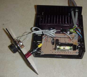
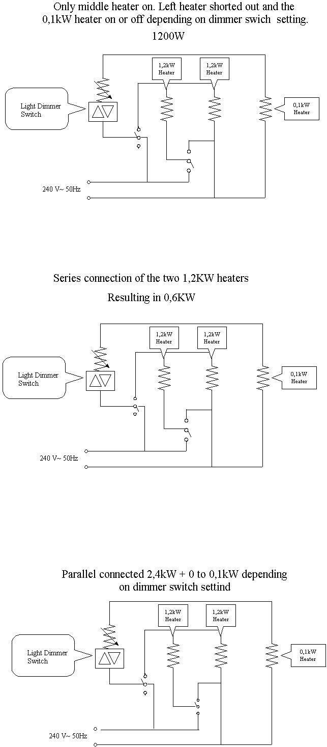
I used to run my old SS-beer barrel with a 0,6 kW immersion heater (the
ones with a 1" BSP male thread on), then I burned it up and found that
they are not made any more, so I decided to buy two 1,2 kW heaters and run
them parallel connected to get up to temperature (2400W) and then
switch them to series = twice the resistance and half the current =
0,6kW.
Here in Queensland you do not need any more if you do not have a lake of
your own for cooling water.
I have also a teeny weeny 100W cartridge element in the barrel, this is
hooked up to an ordinary dimmer switch, so this gives me 600 + (100W
with stepless adjustment for fine tuning).
PS. Dimmer switches can take up to 300W for fine adjustment-heater and
would be better wintertime, but you take what you have ;-)
See schematics below (click to enlarge).
Neils phase angle controller
Neil writes ..
For people wishing to regulate power output of larger power elements (3-6kW) down to a lower power.
Forget large rehostats, variacs etc. Use a 6kW phase angle controller. Search for them on RS components
web site http://rswww.com you will need to find a local agent , or pull info off the attached file and find a
local supplier
Controlling Gas fired Boilers
Craig offers :
I have a gas (propane) fired boiler and control the heat input by measuring the discharge temperature of the condenser cooling water to get an estimate of the heat input to the boiler. The scheme that I use is as follows:
As the boiler is heating up and producing no vapor/steam, I establish a water flow rate through the condenser which is measure by timing the time it takes to fill a 500 ml graduated cylinder. I then convert it to L/min (example 500 ml in 35 sec = .5L/35 sec * 60 sec/min = .875 L/min) and plug that number into the “Flow” variable in my HP 48SX Scientific calculator. Also at this time, I measure the outlet water temperature of the condenser and because there is no heat input into the condenser the inlet temperature (Ti) is equal to the outlet temperature. I plug this temperature into the “Ti” variable in my calculator.
When boiling starts, I cut back on the boiler heat input and from experience I shoot for a condenser outlet temperature say around 55° C. After the outlet temperature has stabilized, I enter this temperature into my calculator and run the program to determine the heat input to my condenser which should closely approximate the heat input to the boiler. While on total reflux, I adjust the boiler heat input to the desired Watts.
I have an Omega digital thermometer with dual inputs. With one of the thermocouples I am able to monitor the head temperature; the other I use to monitor the condenser outlet temperature. Because the thermocouples are of a fine gage, I was able to make pin hole, about chest high, in the clear vinyl tubing (5/16” ID) and insert the thermocouple directly into the condenser outlet water flow stream. This arrangement helps me set and monitor the cooling water flow rate. I adjust the flow to a point where the thermocouple pin hole just quits sucking air into the cooling water flow stream. If flow increases the pin hole leaks water; if it decreases it sucks air.
The calculator is programmed with the following equation:
Q(watts)=Mr×Cp×(Ti-To)
Ti = Condenser Inlet Temperature °C
To = Condenser Outlet Temperature °C
Mr = Condenser H2O Mass Flow Rate Kg/sec
Cp = 4200 (Watts · sec)/(Kg · °C) – Specific Heat of H2O @ approximately 50 °C
The specific program for the HP 48SX calculator is:
Set up the variables “Watt”, “Ti”, and “Flow”
Key in < < Ti-Flow*4200*60 / > > and store it in “Watt”
Store the inlet temperature in “Ti”
Store the flow rate in “Flow”
Enter the outlet temperature into the display
Press the Watt’s key to run the program
The watts should display
Note: The flow, even though measured as a volumetric rate, closely equates to a mass flow rate at the temperature ranges involved (1 Liter H2O ˜ 1 Kg H2O)